All three devices are optosensors; they are electronic devices which alter their electrical characteristics in the presence of light (which may or may not be in the visible range.) In dark conditions the resistance of these devices is high; typically several megohms. In light conditions the resistance falls to typically 30 ohms in bright sunlight. Many practical uses of this property are possible. The circuit diagram shows that the circuit consists of three main stages: Front detector. In dark conditions the MAL12 is virtually an open circuit. No current flows through the potentiometer into the base of the transistor. Thus the transistor is OFF and the logic level on the input line to the 14011 is LOW. The potentiometer gives some control over sensitivity.
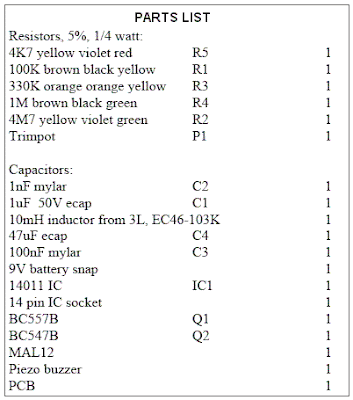
2. The 14011 and the tank circuit. The 14011 is a quad (there are 4 of them), 2 input, NAND gate. It is wired up to oscillate when the input to it goes high, that is the BC557 transistor turns on after light is detected by the MAL12. The oscillating output from the 14011 turns the BC547 on and off. When it is ON the tank circuit (the choke and the piezo buzzer) charges up. When the transistor turns OFF the piezo (which acts as a capacitor) discharges into the choke and makes a 'click' as it does so. Once the piezo is discharged the magnetic field around the choke starts to collapse and recharge the piezo, and the cycle repeats. This is called 'ringing'. Of course there are some resistive losses and the amplitude of the oscillation is slightly less with every cycle. However, the ringing does not decay away completely before the transistor turns on again and recharges the tank circuit fully.
3. After the alarm has been operating and it is put back into dark conditions again then alarm will continue to sound for about 3 - 5 seconds. This is due to the 1uF capacitor & 4M7 resistor which keep the input to the 14011 HIGH. When the voltage falls below about 30% of the rail voltage (9V) the oscillator turns off. To decrease the delay reduce R2.
Light Alarm Assembly
Assembly is straight forward and components may be added to the PCB in any order. It is generally good practice to add the lowest height components first. Only one resistor lies flat on the circuit board. The other three stand upright to save space.


